Some cool wire electrical discharge machining pictures:
Image from page 20 of “Electrical news and engineering” (1891)
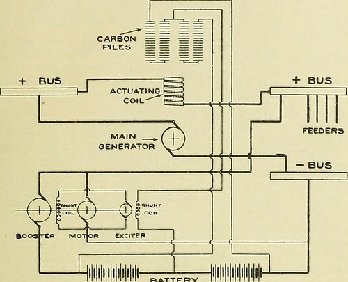
Image by Net Archive Book Pictures
Identifier: electricalnewsen20donm
Title: Electrical news and engineering
Year: 1891 (1890s)
Authors:
Subjects: Electrical engineering
Publisher: Don Mills, Ont. [etc.] Southam-Maclean Publications
View Book Page: Book Viewer
About This Book: Catalog Entry
View All Photos: All Images From Book
Click right here to view book on the web to see this illustration in context in a browseable on the web version of this book.
Text Appearing Before Image:
turers merchandise, but this is the cliloride.So extended as a liattery can be charged at about this rate (in orderto compensate for the discharge), tlien it is tlie suitable batteryto choose. 1 might have stated, A battery capable of maintaining1,400 for 1 hour would preserve a steady generator load of GOOami)eres with a battery capable of becoming discharged at the aboverate and charged at 700 jimperes, becjuise 700 amjieres is a safecharging price for :i battery cnp:ibb of discharging J,400 for onehour. CANADIAN RLECTftlCAL NEWS five in tlie load above or under this fixed geuorator will thereforechange the stress on the carbon piles, resulting in wide varia-tion in their speak to resistance. Advantage is taken of this resistance variation in the carbonpiles to handle the field excitation of the booster via theintermediary of a small exciter, the field of which is the middlewire of a 3 wire program as shown in diagram in Fig. 2. Inexplanation of the diagram, if the pull exerted by the solenoid
Text Appearing Right after Image:
desired amount by varying the tension of the spring at the endof the lever which regulates the stress on the carbon piles.This adjustment is created by a tiny haudwheel and may possibly bealtered from time to time to meet any considerable alterations inthe nature of the load, so that the battery can be either floating,providing continuous pealc discharge, or being charged according tothe adjustment, while constantly automatically taking the moment-ary fluctuations of the load. The output of the exciter is almost infinitesimally modest ascompared with the booster it controls. For a 500 k.w. booster itwould only be 2..five k.w., and it is naturally a quicker operationto reverse a machine for 2.five k.w. than one of 500 k.w. In orderto eliminarte any possibility oflag in reversing, the exciter isdesigned to give three times the excitation volts needed togive the essential increase across the booster armature, therefore ensur-ing instantaneous response, the carbon regulator automaticallythrottling the excess when the co
Note About Pictures
Please note that these images are extracted from scanned page pictures that could have been digitally enhanced for readability – coloration and appearance of these illustrations may not perfectly resemble the original operate.
Image from page 252 of “Journal of electrical energy” (1917)
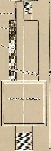
Image by Web Archive Book Images
Identifier: journalofele381151917sanf
Title: Journal of electrical energy
Year: 1917 (1910s)
Authors:
Subjects: Electrical engineering Electrical energy Gas manufacture and operates
Publisher: San Francisco : Technical Pub. Co.
View Book Page: Book Viewer
About This Book: Catalog Entry
View All Pictures: All Pictures From Book
Click here to view book on the internet to see this illustration in context in a browseable on the web version of this book.
Text Appearing Just before Image:
construction of an aluminum jacket castaround a copper tube has been abandoned in favor of asingle homogeneous casting. Coin Machine Manufacturing Conipany Date Tested—January 21, 1916. Type—Induction. Two heaters, No. 35B-109 S. C, No. 35A-55. Volts—110. Amperes—11 and 8.5. 1000 and 750 watt nominal. Heat—Single. General Dimensions—9 in. by 7.75 in. by 6.25 in. Weight—26 lb. Construction—A structure consisting of a copper coil withhollow core of cast iron or steel and laminated iron yokes,arranged somewhat in the order of a shell type trans-former. When the coil is connected to the suitable alter-nating current supply, eddy currents are set up in thecore, which will heat water in get in touch with therewith. The coilis wound with asbestos insulated wire, and is protected byan external cast iron shell. Water comes in direct contactwith heating element. Heat flow is radially inward towater and outward to air along great conducting paths ofmetal. x.~coppn? p/p£. H£AT///S £LEI*EHT~
Text Appearing Right after Image:
Insulation—None. Facilities for Cleaning—None, unless piped with specific tees.Otherwise heater must be disconnected.TestConnections and Method—Standard, % in. circulating pipe.Temperature Head—17° C.Circulation—13 gal. per hr. Efficiency—750 watt heater, 96% decreasing to SS% right after 12 hrs.1000 watt heater, 97% decreasing to, 90% after 12 hrs.Watts Input—At 110 volts, 750 watt heater, 740 to 700 wattsafter 12 hrs. 1000 watt heater, 1050 to 900 watts Energy Factor—At 110 volts, 750 watt heater, 77% to 74% after12 hrs. 100O watt heater, 79% to 80.5% after12 hrs. Surface Temperature—73° C. with water discharging at 64° C. Durability—Heater stood dry test with 150 volts applied forover an hour with out injury. Remarks—The induction heater is most likely the most durableof any created. Its efficiency can be improved by correct lag-ging. The low power element is undesirable. In service ithas been found to make an objectionable hum that istransmitted by the piping to which
Note About Pictures
Please note that these images are extracted from scanned page images that might have been digitally enhanced for readability – coloration and appearance of these illustrations may possibly not completely resemble the original perform.
Image from page 477 of “The street railway overview” (1891)
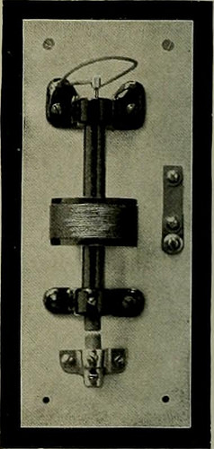
Image by Web Archive Book Photos
Identifier: streetrailwayrev07amer
Title: The street railway assessment
Year: 1891 (1890s)
Authors: American Street Railway Association Street Railway Accountants’ Association of America American Railway, Mechanical, and Electrical Association
Subjects: Street-railroads
Publisher: Chicago : Street Railway Evaluation Pub. Co
View Book Page: Book Viewer
About This Book: Catalog Entry
View All Images: All Photos From Book
Click right here to view book on the web to see this illustration in context in a browseable online version of this book.
Text Appearing Just before Image:
s,such as combinations of zinc andantimony. When a static dis-charge requires place the Hash is in-stantaneous and is not followedb an arc. Tlie lightning dis-charge passes across these airgaps in preference to enteringthe coils of the machine for thesepossess wonderful self-induction to ahighly oscillatory discharge oflightning. Acting on this prin-ciple choke-coils are introduc-ed into the line. These consistof a couple of circular turns in circuitwhich have small self-induction with the normal current andfrequency, but when a lightning discharge is passing overthe line the self-induction becomes quite excellent. Fig. 14represents a lightning arrester produced by the Siemens &Halske Firm for alternating currents of high potential.The distance amongst the wires at the nearest point is about.04 in. for each and every 1,000 volts on the line. When an arc isformed an ascending existing of warm air and the action ofthe current in the wire trigger the arc to rise and break onaccount of the separation of the wires.
Text Appearing After Image:
FIG. 15—GARTONARRESTER. <^ticct5ail*Va^5^ylcW* 465
Note About Images
Please note that these images are extracted from scanned page pictures that may have been digitally enhanced for readability – coloration and appearance of these illustrations may possibly not perfectly resemble the original perform.