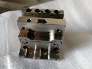
Precision cnc machining parts manufacturer shows the top and the front perspective on a work piece during confronting. Notice how the Z-zero position is 0.100″ beneath the top surface of the unpleasant stock, 0.900″ over the outside of the equals, and the face plant is making a plane at Z-zero. The program code for the confronting procedure on a Fanuc or Haas machine (counting the program start and end) is additionally appeared.
Face factory the top surface of the work piece appeared in the sketch, china precision machined components suppliers are utilizing these bearings:
- Use the lower left-hand corner of the part as the beginning.
- Use a 3″- breadth face-processing shaper and machine from option to left.
- Use a freedom plane of 0.100″.
- Turn on flood coolant (M8) when the apparatus is brought to the leeway plane.
- Face factory at Z0.
- Use an axle speed of 2000 RPM.
- Use a plunging feed pace of 15.0 IPM.
- Use a confronting feed pace of 30.0 IPM.
- End the program by killing coolant (M9), withdrawing to the leeway plane, and moving all tomahawks to home positions. The past model just confronted one side of the part.
Frequently, the part drawing requires both the top and the base surfaces to be confronted and a particular thickness to be accomplished.
This requires a M0 program stop and the part to be flipped physically in the wake of confronting the main side. Enough thickness should be left when side one is confronted so that side two can likewise be confronted. After side two is confronted, the part ought to be at its last thickness. The confronting pass on side one is customized at a Z-positive position. After the part is flipped, the confronting pass for side two is modified at Z-zero. At the point when the machine is set up, Z-zero should be painstakingly set with the goal that the last confronting pass liable for completing the part thickness additionally makes the Z-zero plane. The model beneath shows ventures for confronting a section to thickness, including a section flip. Likewise with the past model, the stock is 1.0″ thick and the objective thickness is 0.900″. Here, as well, the Z-zero should be set 0.100″ underneath the top surface of the unpleasant stock (1.0 – 0.900 = 0.100). It is a smart thought to eliminate equivalent sums from each side. Since 0.100″ of complete material should be eliminated, 0.050″ will be taken from each side (0.100″/2 = 0.050″).
CNC machined part factory shows the top and front perspective on a work piece during confronting. Notice how the Z-zero position is underneath the top surface of the unpleasant stock on side one, and the face factory is making a plane at a positive Z-position. This leaves material to be looked on the opposite side of the part after it has been flipped.
The part consistently lays on the equals, so the space between the top surface of the equals and the Z-zero position is the last part thickness. Notice the front perspective on a work piece during looking of side two. The Z-zero position is beneath the top surface of the unpleasant stock, yet the face plant is situated at Z-zero and is making a machined surface at that position. The program code for a Fanuc or Haas machine is likewise appeared and incorporates a program stop with the goal that the machining cycle is stopped for the part-flip.
This article is from http://www.cncmachinings.com/
