Some cool electron discharge machining images:
Image from page 62 of “Practical electro-therapeutics and X-ray therapy : with chapters on phototherapy, X-ray in eye surgery, X-ray in dentistry, and medico-legal aspect of the X-ray” (1912)
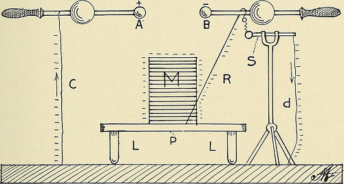
Image by Internet Archive Book Images
Identifier: practicalelectro00mart
Title: Practical electro-therapeutics and X-ray therapy : with chapters on phototherapy, X-ray in eye surgery, X-ray in dentistry, and medico-legal aspect of the X-ray
Year: 1912 (1910s)
Authors: Martin, James Madison, 1866-1947
Subjects: Electrotherapeutics X-rays Diagnosis, Radioscopic Eye Electric Stimulation Therapy X-Ray Therapy Ophthalmologic Surgical Procedures
Publisher: St. Louis : C.V. Mosby
View Book Page: Book Viewer
About This Book: Catalog Entry
View All Images: All Images From Book
Click here to view book online to see this illustration in context in a browseable online version of this book.
Text Appearing Before Image:
ddition of negative charges anda like momentarily weakening of the negative charges on B. Theincrease of the negative charges on A increases the negative charge ELECTROSTATICS 59 on the inside coat of Leyden jar Ll, while the discharge of B weak-ens the negative charges on the inside coating of Leyden jar L2.At this instant the electrons that have collected in considerablenumbers on the outside coating of Leyden jar Ll will returnthrough the conducting cord Gl, electrode HI, the patient M, elec-trode H2, conducting cord G2, and back to the outside coating ofLeyden jar L2, to be forced away again as soon as the jar L2 hasits inner coating negatively charged. The whole process takesonly the smallest possible fraction of a second, and because of itsrapid change in direction the current is a truly interrupted cur-rent, simulating closely the faradic current and used mainly forthe same class of cases. It is claimed that the oscillations in thecurrent are from 200,000 to 300,000 per second.
Text Appearing After Image:
Fig. 28.—Arrangement for potential alternation. Patient negative. (6) Potential Alternation.—This particular arrangement ofstatic machine, patient, and electrode was first suggested by Doc-tor S. H. Monell in 1893. It differs very little from the Mortonwave current, to be described, and has no advantage over it in thetreatment of any case. It is seldom used, but is here describedbecause sometimes spoken of in papers and text-books. Fig. 28 shows the arrangement of static machine, electrode, andpatient to produce the effect known as potential alternation. Itdiffers mainly from the Morton wave in the spark gap, which, in-stead of being between the prime conductors, is between the sta-tionary electrode and the ball on the shepherds crook on the prime 60 PRACTICAL ELECTRO-THERAPEUTICS AND X-RAY THERAPY conductor B. In this arrangement the overcharge on the patient Moverflows to the stationary electrode S and on to the ground throughconducting wire d. This condition is true when the pa
Note About Images
Please note that these images are extracted from scanned page images that may have been digitally enhanced for readability – coloration and appearance of these illustrations may not perfectly resemble the original work.
Image from page 61 of “Practical electro-therapeutics and X-ray therapy : with chapters on phototherapy, X-ray in eye surgery, X-ray in dentistry, and medico-legal aspect of the X-ray” (1912)
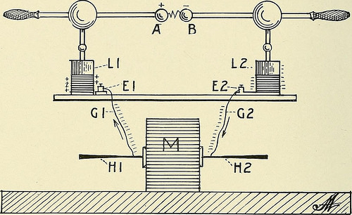
Image by Internet Archive Book Images
Identifier: practicalelectro00mart
Title: Practical electro-therapeutics and X-ray therapy : with chapters on phototherapy, X-ray in eye surgery, X-ray in dentistry, and medico-legal aspect of the X-ray
Year: 1912 (1910s)
Authors: Martin, James Madison, 1866-1947
Subjects: Electrotherapeutics X-rays Diagnosis, Radioscopic Eye Electric Stimulation Therapy X-Ray Therapy Ophthalmologic Surgical Procedures
Publisher: St. Louis : C.V. Mosby
View Book Page: Book Viewer
About This Book: Catalog Entry
View All Images: All Images From Book
Click here to view book online to see this illustration in context in a browseable online version of this book.
Text Appearing Before Image:
nt positive. (5) Static Induced Current.—This current was first described byDoctor W. J. Morton in 1880. The prime conductors are con-nected with the inside coating of the Leyden jars and the patientwith the outside coatings by means of two conducting cords and 58 PRACTICAL ELECTRO-THERAPEUTICS AND X-RAY THERAPY electrodes. Fig. 27 represents this arrangement. A and B arethe prime conductors, Ll and L2 are the Leyden jars, El andE2 are the binding posts connected to the outside coatings of thejars, Gl and G2 are the conducting cords, HI and H2 are theelectrodes, and M is the patient. It is not necessary to placethe patient on the insulated platform. When the machine is started,electrons flow from the negative prime conductor B into Leydenjar L2, making it strongly negative. Electrons are forced awayfrom the outside coating of this jar through conducting cord G2and electrode H2 to the patient M. The electrons leave the pa-tient through electrode HI, conductor Gl, and binding post El,
Text Appearing After Image:
Fig. 27.—Static induced current. and to the outside coating of Leyden jar Ll, making it stronglynegative. The action of the static machine, already explained,takes the electrons from the prime conductor A and the insidecoating of Leyden jar Ll, making them strongly positive. Thestrength of this current is controlled by the speed of the revolvingplates and size of the Leyden jars. This current is oscillating incharacter, playing backward and forward through the patient be-tween the outer coatings of the Leyden jars. When a sparkjumps across the air gap from B to A, the positive charge on Ais momentarily neutralized by an addition of negative charges anda like momentarily weakening of the negative charges on B. Theincrease of the negative charges on A increases the negative charge ELECTROSTATICS 59 on the inside coat of Leyden jar Ll, while the discharge of B weak-ens the negative charges on the inside coating of Leyden jar L2.At this instant the electrons that have collected in consi
Note About Images
Please note that these images are extracted from scanned page images that may have been digitally enhanced for readability – coloration and appearance of these illustrations may not perfectly resemble the original work.
Image from page 94 of “The principles and practice of roentgenological technique” (1920)
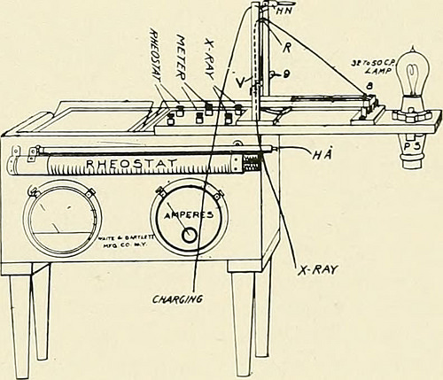
Image by Internet Archive Book Images
Identifier: principlespracti00hirs
Title: The principles and practice of roentgenological technique
Year: 1920 (1920s)
Authors: Hirsch, Isaac Seth, 1889-1942
Subjects: Radiography
Publisher: New York, American X-Ray Pub. Co.
View Book Page: Book Viewer
About This Book: Catalog Entry
View All Images: All Images From Book
Click here to view book online to see this illustration in context in a browseable online version of this book.
Text Appearing Before Image:
^;l!l!llt- B A Fig. 87.—Coolidge tube circuit B is the storage bat-tery, A is the ammeter, R is the rheostat forregulation of the battery current. The doublewires go to the cathode end of the tube. Mis the milliamperemeter. possible and in such a way that it can be easilyread from the operating position. If the polarity of the machine is wrong, it
Text Appearing After Image:
Fig. 88.—Storage battery arrangement for Coolidgetube with attachment for charging. When theextension to the right is placed vertically thebattery charges. (Waite and Bartlett). will be shown by the fact that the milliam-meter will register no current, regardless ofhow high the filament temperature may be. Before the tube can be energized it is neces-sary to heat the filament. 70 ENERGIZATION OF COOLIDGE TUBE No discharge current through the tube cantake place unless the filament is heated,and the amount of discharge current whichmay be passed into the tube is determined pri-marily by the degree of heating of the fila-ment. If the temperature of the filament is low,only a small number of electrons escape fromit and, consequently, only a small dischargecurrent can be sent through the tube. Themaximum current for each particular filamenttemperature is called the saturation currentwhich means that all the electrons are beingutilized as fast as they are produced. Increas-ing the impress
Note About Images
Please note that these images are extracted from scanned page images that may have been digitally enhanced for readability – coloration and appearance of these illustrations may not perfectly resemble the original work.