A few nice wire electrical discharge machining China images I found:
Image from page 244 of “[Electric engineering.]” (1902)
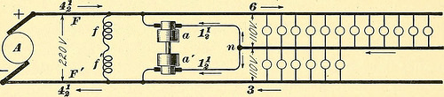
Image by internetarchivebookimages
Identifier: electricengineer03inte
Title: [Electric engineering.]
Year: 1902 (1900s)
Authors: International Library of Technology
Subjects: Electrical engineering
Publisher: Scranton, International Textbook Co.
View Book Page: Book Viewer
About This Book: Catalog Entry
View All Images: All Images From Book
Click here to view book online to see this illustration in context in a browseable online version of this book.
Text Appearing Before Image:
20-volt dynamo isconnected to the outside wires, and if a larger current isneeded on one side of the battery than on the other, theextra current is supplied from the battery. It is not, how-ever, generally advisable to use a battery in this way formaintaining the balance continuously as the cells becomeunevenly discharged. When batteries are used on three-wire systems, they are usually connected across the outsidelines and a switch provided to connect their middle point withthe neutral, so that they can be used for balancing in caseof necessity. 5(y. Fig. 29 shows a three-wire system fed by a 220-voltdynamo A in conjunction with a motor-dynamo a a. Thismotor-dynamo is sometimes called a balancing set or bal-ancer. The armatures a, a are mounted on the same shaftand connected in series, the mid-point n being connected tothe neutral wire. The fields of these two machines are con-nected across the mains, as shown at//. When one sideof the system is more heavily loaded than the other, the
Text Appearing After Image:
Fig. 29. machine on the heavily loaded side runs as a dynamo and helps to supply current to that side, while the machine on the lightly loaded side absorbs power and runs as a motor, thus equalizing the load. Take, for example, the special case shown in Fig. 29, where we have 12 lamps on one side and 6 on the other. We will have 18 lamps to be supplied with power from the 220-volt machine A. Allowing 55 watts , • • „ j i 55 X 18 per lamp, this gives 55 X 18 watts and, hence, ———— = 4r| amperes. The current flowing out on F and back § 16 ELECTRIC LIGHTING. 47 on F must, therefore, be 4£ amperes. The upper side ofthe three-wire system requires 6 amperes and the lowerside 3, because we have 12 lamps in parallel in the one caseand 6 in the other. We have, then, 3 amperes coming backthrough the neutral, of which 1^ flows through a, runningit as a motor and generating 1| amperes in a. This amperes is added to the 4|- in line F, thus making the6 required for the upper side.
Note About Images
Please note that these images are extracted from scanned page images that may have been digitally enhanced for readability – coloration and appearance of these illustrations may not perfectly resemble the original work.
Image from page 366 of “[Electric engineering.]” (1902)
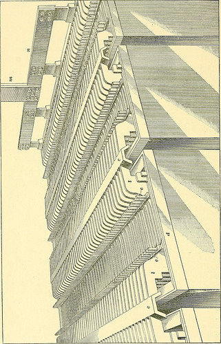
Image by internetarchivebookimages
Identifier: electricengineer03inte
Title: [Electric engineering.]
Year: 1902 (1900s)
Authors: International Library of Technology
Subjects: Electrical engineering
Publisher: Scranton, International Textbook Co.
View Book Page: Book Viewer
About This Book: Catalog Entry
View All Images: All Images From Book
Click here to view book online to see this illustration in context in a browseable online version of this book.
Text Appearing Before Image:
adlining and e, e are glass rods for separating the plates; m, n arethe heavy copper conductors leading from the battery. Thespace occupied by a battery for a given output will dependon the way in which the cells are arranged, i. e., whether inone or two tiers. Generally, however, 1,000 kilowatt-hourscan be stored per 100 square yards of space. The numberof cells required in an installation will depend on the volt-age to be supplied. In large central stations operating onthe three-wire 110-220-volt system, about 80 cells are used oneach side of the circuit, though the exact number of cellsdepends considerably on the range of voltage required tomeet special conditions. 64. Regulation of Batteries.—In order to fully chargethe cells, it is necessary to have a voltage somewhat higherthan that on which the system is ordinarily run. Of course,this might be obtained by running the generators at a highvoltage, but in most cases this is not practicable, because the 74 ELECTRIC LIGHTING. §17
Text Appearing After Image:
§ 17 ELECTRIC LIGHTING. 75 machines are generally used to supply current for lightingat the same time that they are charging the cells. In order,then, to raise the voltage on the battery, a booster isused when charging is going on. In lighting work, thebooster is not generally used for regulating purposes, butsimply to add enough pressure to the dynamos to enablethem to charge the batteries. In railway work, where theload fluctuates very rapidly, the booster is so constructed asto make the battery discharge when the load is heavy andcharge up when it is light. In lighting plants, the booster isusually shunt-wound or compound-wound and is driven by amotor. Fig. 71 shows one scheme of connections. Only theessential parts are here shown, so as to illustrate the principlesinvolved without confusing the diagram with the variousinstruments and switches. For this reason, also, a simpletwo-wire system is illustrated. G is the generator supply-ing current to the lamp load L. A is the battery
Note About Images
Please note that these images are extracted from scanned page images that may have been digitally enhanced for readability – coloration and appearance of these illustrations may not perfectly resemble the original work.