A couple of nice precision engineering services pictures I located:
Image from page 1147 of “Electrical world” (1883)
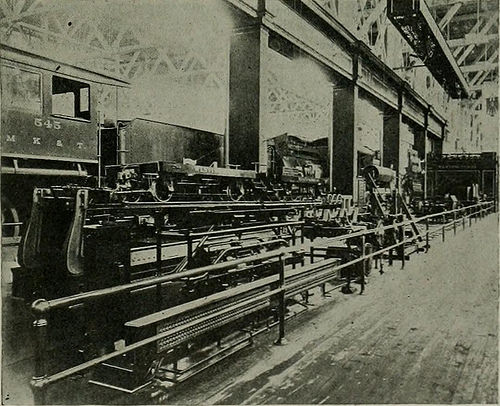
Image by Internet Archive Book Photos
Identifier: electricalworld43newy
Title: Electrical world
Year: 1883 (1880s)
Authors:
Subjects: Electrical engineering
Publisher: [New York McGraw-Hill Pub. Co., etc.]
Contributing Library: Engineering – University of Toronto
Digitizing Sponsor: University of Toronto
View Book Page: Book Viewer
About This Book: Catalog Entry
View All Images: All Images From Book
Click here to view book on-line to see this illustration in context in a browseable online version of this book.
Text Appearing Just before Image:
or belt ordirect connection rotary converters, motor-generator sets, oil-in-sulated and air-blast transformers, direct-current and alternating-existing railway motors and controllers, single and polyphase in-duction motors of continuous and variable speeds, direct-present motorsof numerous kinds, including motors for variable-speed service fromsingle and double-voltage circuits, switchboard apparatus, ammeters,voltmeters, wattmeters, synchroscopes, power aspect meters, circuit-breakers and switches, several of them electrically operated portableinstruments, instruments of precision, potential regulators, and innu-merable other forms of auxiliary apparatus and instruments. Thealternating-present, series-wound, single-phase crane motors, sim-ilar in sort and basic building to the single-phase railwaymotors exhibited in the Transportation Developing, and the new West-inghouse Unit Switch Technique of Several Manage are also to heseen in this section. The spectacular higher-tension sign, utilizing a
Text Appearing Following Image:
FIG. 5.—BRAKE E.XHIBITS, TRANSPORTATION Building. brake which is now so a lot in use. The method at present gen-erally adopted when two pumps are employed on 1 locomotive isshown, and 1 of the novel characteristics of the rack is that all valvesare placed ig duplicate, a single sectioned so as to show the internalworking mechanism, and connected to the valve in use in such a ELECTRICAL Globe and ENGINEER. Vol. XLIII, No. 24. manner that it moves as the regular valve is operated. The opera-tion of the various valves is thus readily studied. The Westinghouse friction draft gear also is shown in section,with a machine particularly made for testing it in operation. Theavailable power which can be e.xerted on the draft gear approximates2,000 pounds. A triple valve testing rack is presented to show themanner in which this device is now becoming installed in several rail-road shops. Sectional components also are shown of the other apparatusof the Westinghouse Air Brake Company and the WestinghouseTraction Brake
Note About Images
Please note that these images are extracted from scanned web page images that might have been digitally enhanced for readability – coloration and look of these illustrations could not completely resemble the original work.