Check out these swiss screw machining images:
Image from page 380 of “Modern mechanism, exhibiting the latest progress in machines, motors, and the transmission of power, being a supplementary volume to Appletons’ cyclopaedia of applied mechanics” (1892)
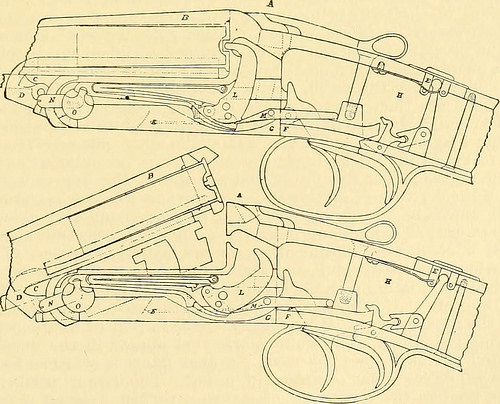
Image by Internet Archive Book Images
Identifier: modernmechanisme00benj
Title: Modern mechanism, exhibiting the latest progress in machines, motors, and the transmission of power, being a supplementary volume to Appletons’ cyclopaedia of applied mechanics
Year: 1892 (1890s)
Authors: Benjamin, Park, 1849-1922
Subjects: Mechanical engineering
Publisher: New York, D. Appleton
View Book Page: Book Viewer
About This Book: Catalog Entry
View All Images: All Images From Book
Click here to view book online to see this illustration in context in a browseable online version of this book.
Text Appearing Before Image:
cartridge-rim. We learn from the official hand-book of the Swiss Mili-tary Department that the rifle will fire 20 aimed shots a minute when used as a single loader.With the magazine in action it will fire 30 aimed shots in the same time, and 40 shots with-out aiming. The successive shots can be fired without removing the rifle from the shoulder.The weight is 9^ lbs. The total length of the barrel is 307 in.; the caliber, 295 in.; thenumber of grooves in the rifling is 3, and they make one turn in 106 in. The bullet is ofhardened lead, in a steel envelope; its length is 113 in., its diameter 32 in., and its weight•0302 lb. The charge of smokeless powder is 31 grains. This gives an initial velocity of1,968 ft. a second. A full description of the mechanism of this arm appears in Engineering China,October 2, 1891. II. Shot-Guns.—The Colt Hammerless Gun is shown open in Fig. 13 and closed in Fig. 14.The parts are as follows: A is the frame, B the barrel, C the fore-end, D the extractor cam,
Text Appearing After Image:
Figs. 13, 14.—Colt hammerless gun. E the safety-slide, F the trigger-plate. G the lock-cover plate, H the stock, / the screw-holesin the draw-bar, J the mainspring. K, the sear-spring, L the hammer, 31 the sear, N thecocking-pin, and 0 the body-pin. The operation is as follows: The gun is cocked first bythrowing down the barrels, and second by bringing them back into place. An inspection ofthe drawing shows that the second motion increases the tension of the mainspring by push- 360 FIKE-ARMS. ing its inclined surface above the roll of the hammer, thus utilizing both motions of the bar-rels and making the forces required to open and close them more nearly equal. The main-springs move on rolls, making the friction tlie least possible. The safety apparatus doesnot require the cutting away of the stock, .so that the stock is very strong. The triggersare firmly secured by a positive-lock and not by springs. The hammers can be let downseparately or together by pressing the safety-slide fo
Note About Images
Please note that these images are extracted from scanned page images that may have been digitally enhanced for readability – coloration and appearance of these illustrations may not perfectly resemble the original work.
Image from page 303 of “Mechanical appliances, mechanical movements and novelties of construction; a complete work and a continuation, as a second volume, of the author’s book entitled “Mechanical movements, powers and devices” … including an explanator
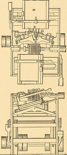
Image by Internet Archive Book Images
Identifier: mechanicalapplia01hisc
Title: Mechanical appliances, mechanical movements and novelties of construction; a complete work and a continuation, as a second volume, of the author’s book entitled "Mechanical movements, powers and devices" … including an explanatory chapter on the leading conceptions of perpetual motion existing during the past three centuries
Year: 1910 (1910s)
Authors: Hiscox, Gardner Dexter, 1822?-1908
Subjects: Mechanical movements
Publisher: New York, The N. W. Henley publishing company
View Book Page: Book Viewer
About This Book: Catalog Entry
View All Images: All Images From Book
Click here to view book online to see this illustration in context in a browseable online version of this book.
Text Appearing Before Image:
es of the mor-tise, and of any angle that may be re-quired, by adjusting the stays in which thecutters are hung to the required angle. The central cutter, H, as will be seen,cuts into the board at a right line be-tween the side saws, and as it leads inthe cutting, the central portion of the mor-tise is cut away ; the side saw^s, as theyfollow, cut away the remainder, leavinga clean, angular mortise for the admissionof the tenon. 798. Elevation, showing saws and angle of board to be dovetailed. 799. DIAMOND MILLSTONE-DRESSING MACHINE. A Swiss machine lor dressing millstones. The frame, A, has arms, h, b, terminating in feet, c, which areprovided with set screw^s. A toolsupport, S, is pivoted to the centerof A, and is adjustable by means ofsector, B, and slides on the arm, C,of the frame. Two disks at K carrydiamonds on their peripheries,and are set in rapid revolutionby belts from spindle, J, which isrevolved from any convenientshaft outside the millstone.The cutting disks being put in
Text Appearing After Image:
Note About Images
Please note that these images are extracted from scanned page images that may have been digitally enhanced for readability – coloration and appearance of these illustrations may not perfectly resemble the original work.